Phone:
+254 719 428 550
Physical address:
Information House, Hakati Road,
Nairobi, Kenya.
Phone:
+254 719 428 550
Physical address:
Information House, Hakati Road,
Nairobi, Kenya.
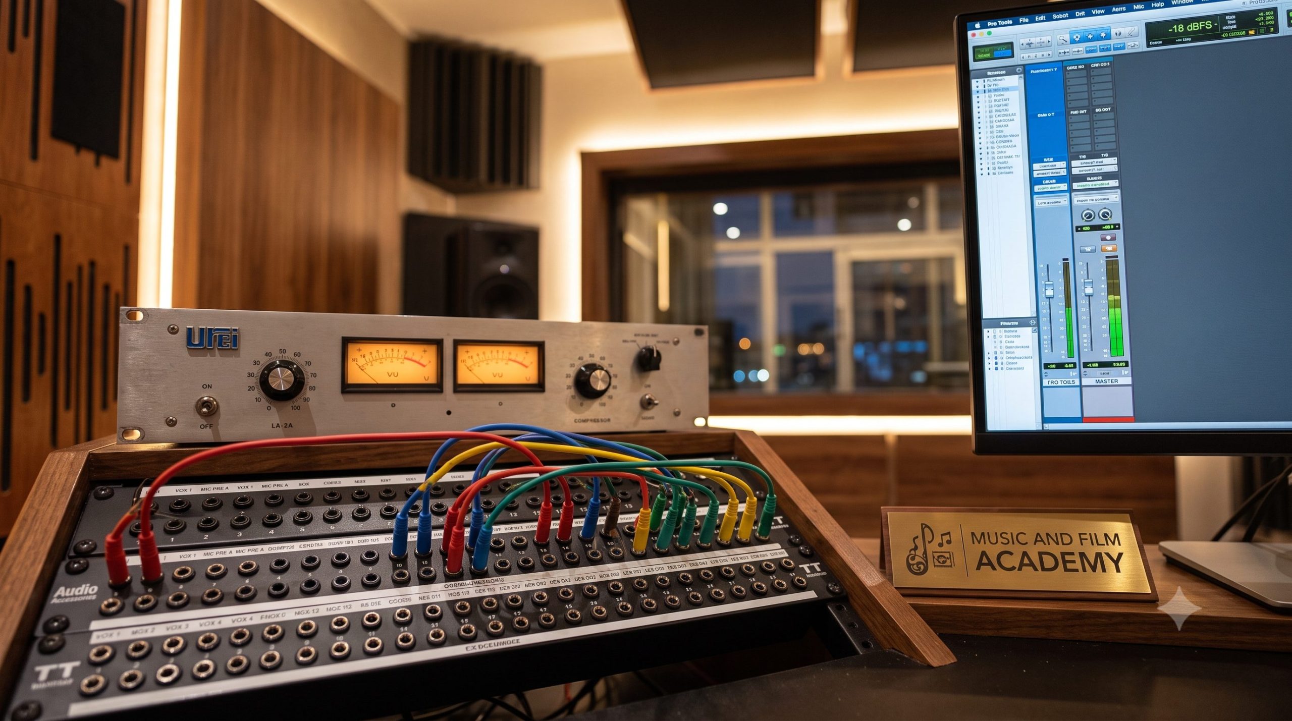
For decades, the image of a commercial recording space has been defined by a massive, multi-million-shilling analogue mixing console stretching across the control room. Many legacy media institutions and digital arts colleges across Nairobi lean heavily on this imagery for marketing, positioning their large-format boards as the ultimate standard for professional audio training. However, as we navigate the music industry landscape of 2026, a fundamental shift has occurred. The global recording ecosystem has transformed, and relying blindly on the aesthetic appeal of an expensive console can leave a student structurally unprepared for the realities of modern engineering. If your ambition is to operate seamlessly in any modern production environment, focusing on mastering signal flow in commercial studios is infinitely more valuable than learning to operate one specific brand of hardware console.
The modern debate between traditional analogue desk mixing and modern “In-The-Box” (ITB) digital audio workstation (DAW) processing is no longer about which system is better; it is about understanding how to bridge the two worlds efficiently. Top-tier hitmakers worldwide rarely work exclusively in one domain. Instead, they build highly flexible hybrid networks that combine the flawless speed and total recall of digital plugins with the unique harmonic distortion and depth of external hardware gear. To manage this hybrid environment without causing severe technical issues like ground-loop hums, phase cancellation, or digital clipping, an engineer must possess a solid, mathematical understanding of audio paths. This comprehensive guide strips away the marketing hype surrounding large consoles, breaking down patchbay configurations, mic/line switch physics, gain staging principles, and exactly how to route physical compressors and reverbs into a modern DAW pipeline.
1. Demystifying the Routing Engine: The Architecture of the Studio Patchbay
The nerve center of any professional recording facility is not the computer or the mixing board; it is the patchbay. When you look past the basic cosmetic layout of an engineering room, the patchbay serves as the centralized access matrix that physically exposes every single audio input and output channel available in your facility. If you fail to master the underlying physics of patchbay normalization, you will struggle with routing signals safely.
[Row A: Outpu] ───► (Internal Normal Connection) ───► [Row B: Inputs]
│ │
└──► [Inserting a Patch Cable Breaks the Loop] ◄──────┘
Understanding Normalled, Half-Normalled, and Thru Configurations
A standard professional patchbay (typically using 96-pin TT/Bantam or 1/4-inch TRS connections) is divided into two distinct horizontal layers: the top row is dedicated strictly to Outputs (signals leaving gear), and the bottom row is dedicated strictly to Inputs (signals entering gear). How these two rows interact internally determines your signal flow architecture:
2. Mic/Line Switch Physics and the Foundation of Gain Staging Principles
A widespread mistake that amateur engineers make when managing a hybrid pipeline is a fundamental misunderstanding of signal levels and impedance matching. If you route an audio signal into the wrong input impedance layout, you will introduce intense distortion or a high noise floor that ruins your tracks.
A. The Structural Differences Between Mic Level and Line Level
Before a sound wave can be processed inside your computer, it exists as a small electrical signal traveling through a copper cable. The level of this voltage dictates its category:
[Mic Capsule: -60 dBu] ──► [Preamp Gain Boost] ──► [Line Level Target: +4 dBu / 0 VU]
When mastering signal flow in commercial studios, you must verify the state of your input selection switches. If you route a line-level signal coming out of an external hardware compressor directly into a patchbay point configured for a microphone preamplifier without activating the line-level padding switch, you will overload the input transistors. This causes harsh, unpleasant square-wave distortion because the input circuit is expecting a tiny millivolt signal but receiving a heavy professional voltage stream instead.
B. Practicing Disciplined Gain Staging Across Hybrid Pathways
Gain staging is the deliberate optimization of signal-to-noise ratios across every independent amplification stage within your audio path. In the old days of tracking strictly on tape, engineers had to push signals hard against a high background tape hiss to get a clean recording. In the modern 24-bit or 32-bit float digital domain, your background noise floor is practically non-existent, meaning you do not need to record hot signals near the red clipping zone.
When tracking or mixing through a hybrid pipeline, your target reference value on an analogue VU (Volume Unit) meter should hover around 0 VU, which is mathematically calibrated to equal +4 dBu. Inside your digital DAW mixer meters, this analogue target translate roughly to -18 dBFS (Decibels Relative to Full Scale). By maintaining your average tracking and processing levels around -18 dBFS, you leave ample digital headroom for transient peaks, prevent your analog hardware components from clipping, and ensure your digital plugins operate within their optimal mathematical design lines.
3. Step-by-Step Blueprint: Integrating External Outboard Gear into Your DAW
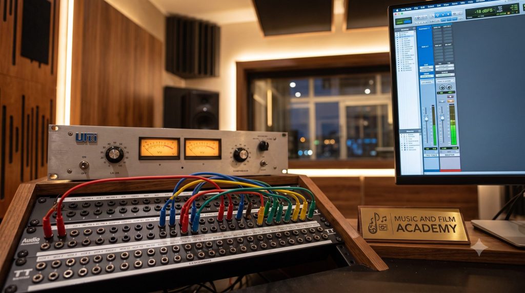
To build a professional hybrid mixing setup, you must understand how to construct an external insert loop within your software that routes audio out to a physical piece of hardware and pulls it back in without causing phase alignment issues.
[DAW Audio Track] ──► [Interface Output 3] ──► [Patchbay Top: Out 3] ──► [Hardware Compressor Input]
│
[DAW Processed Track] ◄── [Interface Input 3] ◄── [Patchbay Bottom: In 3] ◄── [Hardware Compressor Output]
The Hybrid Insert Loop Setup
Follow this precise patchbay and routing sequence to patch a physical compressor or reverb unit into an active software timeline track:
| Signal Flow Component | Connection Type | Target Impedance Standard | Primary Functional Role |
| Top Row Patchbay Point | Bantam / TRS Output | Low Impedance Output | Sends audio out from interfaces, console channel sends, or outboard processing outputs. |
| Bottom Row Patchbay Point | Bantam / TRS Input | High Impedance Input | Receives inbound audio into preamps, interface converters, or outboard hardware inputs. |
| Hardware Insert Plugin | Digital DAW Control | Software Calibrated Matrix | Manages the internal digital routing loops and compensates for round-trip converter latency automatically. |
💡 The MFA Factor: Understanding the math behind latency alignment and impedance calibration can feel overwhelming when staring at a wall of cables. At the Music And Film Academy, our training philosophy is built on mastering the universal physics of signal flow rather than memorizing one specific model of gear. Our hands-on Sound Engineering Courses in Kenya ensure you build deep foundational knowledge, giving you the confidence to walk onto any commercial stage or studio console worldwide.
4. Advanced System Calibration: Eliminating Ground Loops and Phase Distortion
When connecting multiple independent electrical devices into a centralized patchbay network, you will frequently encounter severe background noise issues that can ruin your audio fidelity if left unmanaged.
1. The Engineering of Ground Loops
A ground loop occurs when two or more interconnected electrical devices have separate paths to the studio’s main electrical ground, creating an unintended closed loop for electrical current. This loop captures stray electromagnetic field energy from surrounding power grids, translating it into a loud background hum at 50 Hz (the standard frequency of the Kenyan power grid).
2. Eliminating Inter-Channel Phase Distortion
When tracking an instrument with multiple microphones (such as an acoustic drum kit or a stereo grand piano), the sound waves will arrive at each microphone capsule at slightly different times due to the distance between them. If you mix these individual channels together without checking their phase alignment, these tiny time differences can cause comb filtering, causing your low-end frequencies to thin out dramatically.
[PHASE ALIGNMENT AUDIT LOOP]
│
┌───────────────────────┴───────────────────────┐
▼ ▼
[Engage Polarity Invert (180 degree)] [Evaluate Low-End Response]
│ │
Flips the audio wave profile Choose the position that delivers the
to check time alignment over multiple mics punchiest, fullest bass weight profile
💡 The MFA Factor: Building true technical authority requires extensive, real-world practice under variable conditions. If you want to move past simple bedroom production setups and step into high-volume commercial engineering, learn to manage advanced multi-mic configurations and hybrid studio networks by enrolling in our flagship Certificate in Sound Engineering Course track.
5. Building Long-Term Asset Value Through Standardized Technical Documentation
Maintaining an organized technical tracking layout is a critical skill that separates professional recording studios from amateur setups. It ensures your client projects remain accessible and editable for years to come.
The Professional Strategic Value of Recall Documentation
In a professional commercial studio environment, clients frequently return months after a session is finished requesting small adjustments, such as pulling a lead vocal up by +0.5 dBu or increasing a snare drum’s hardware compression ratio. If you processed that project through a complex analogue outboard chain without maintaining precise documentation, replicating that exact sonic signature becomes impossible.
Professional engineers utilize standardized tracking documentation templates, often called Recall Sheets. These templates contain detailed graphical layouts of your outboard gear faceplates, patchbay paths, and preamp gain steps.
[Session Completed] ──► [Fill Out Detailed Recall Sheet] ──► [File with Master Session Archive] ──► [Guarantees Flawless Analogue Reconstruction]
6. Conclusion: Build Your Technical Foundation on Lasting Scientific Truth
Succeeding as a high-level sound engineer or music producer in today’s industry requires moving past superficial marketing hype and dedicating yourself to mastering signal flow in commercial studios. By understanding the structural architecture of patchbays, matching your mic and line-level inputs properly, practicing disciplined gain staging principles, and learning to manage hybrid hardware-software insert paths, you gain complete control over your creative environment. This deep technical knowledge ensures you are not limited by a single piece of software or model of mixing board.
True professional confidence is built through hands-on practice inside industry-grade acoustic spaces using premium professional equipment. At the Music And Film Academy (MFA), we reject superficial training methods. Our campus facilities at Information House in the Nairobi CBD provide our students with comprehensive, TVETA-accredited tracks designed to build lasting technical competence. You learn to handle complex live routing, calibrate advanced hybrid networks, and manage high-volume client projects using our modern campus tracking rooms and software labs. Stop letting uncalibrated setups bottleneck your creative vision. Take control of your career, upgrade your sound engineering skills, and enroll with us today.